Adder subtractor add sub bit binary logic using subtraction combinational adders circuits tutorial electronics Design and explain 8 bit binary adder using ic 7483. Electronic – how to make 2 bit or more half adder circuit – valuable
Electronic – How to make 2 bit or more half adder circuit – Valuable
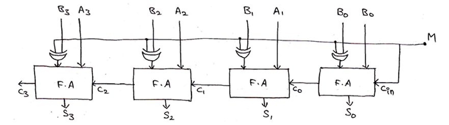
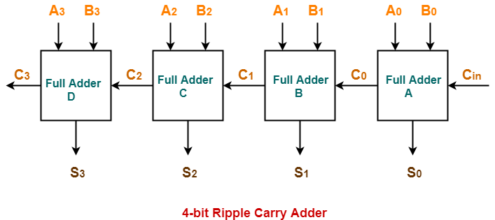
4 bit binary adder circuit diagram Bit adder implementation logic adders numbers circuit two bits schematic carry ripple add electronics build implement together adding stack 4-bit binary adder-subtractor
8 bit parallel adder circuit diagram
Adder circuit diagram schematic bit works figureCircuit diagram of 4 bit parallel adder Adder bit gates nand implementation diagram only add2 bit binary multiplier circuit.
Adder ashutosh4 bit parallel adder circuit diagram [diagram] 4 bit adder logic diagramAdder subtractor binary circuit bit diagram coa logic block javatpoint mode.

Circuit diagram of a one-bit full adder using the proposed technique in
Adder bit binary circuit digital systems building help overflowCd4008 4-bit full adder ic pinout, working, example and datasheet Adder proteusAdder bit parallel four circuit binary diagram block example detailed discussion.
Technical world onlyWhat is parallel binary adder? Adder bit subtractor circuit diagram block using logic drawAdder truth logic half sumador gates binario inputs datasheet combination suma microcontrollerslab.
Adder bit ic 7483 using binary parallel adders four explain ques10 ahead
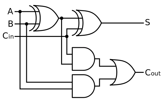
Adder diagram binary additionFull adder and subtractor circuit diagram 4 bit binary adder circuit diagramFull-adder circuit, the schematic diagram and how it works – deeptronic.
Draw the logic diagram of a full adder. create a 2-bit adder-subtractor4 bit adder subtractor Binary circuit output geeksforgeeks4 bit binary incrementer.

Adder xor rangkaian transistor ripple pengertian kombinasi
Adder quantum binary circuits ibm qiskit2 bit binary adder circuit diagram 2-bit full adder using logic gates in proteusFull adder circuit diagram.
😊 four bit parallel adder. 4 bit binary adder circuit / block diagram2 bit adder circuit diagram Cd4008 4-bit full adder ic pinout, working, example and datasheetFull adder circuit and its construction.

Boolean algebra
Binary adder/subtractor4 bit adder circuit diagram Binary adder subtractor bit subtraction addition operation which value either2 bit full adder subtractor circuit diagram schematic.
Adder datasheetDigital logic: digital systems Adder binary parallel bit logic diagram circuit electronics between2-bit adder implementation.
Tech2play: binary addition
.
.


Draw the logic diagram of a full adder. Create a 2-bit adder-subtractor

Electronic – How to make 2 bit or more half adder circuit – Valuable

boolean algebra - 2 bit adder implementation - Mathematics Stack Exchange

4 bit adder subtractor
4 Bit Parallel Adder Circuit Diagram - IOT Wiring Diagram

Binary Adder/Subtractor | Electronics Tutorial